

Draw A Simple Brake Light Circuit

The circuit explained here is presented in response to a request sent by one of the avid readers of this blog. The proposed circuit is of a sequential LED light driver, especially designed to suit the application of a multipurpose car tail light indicator.
Circuit Connections
The circuit is integrated to the brake switch and works as a brake light, it's also connected to the turn signal switches for indicating the turning of the vehicle with chasing light patterns, and the circuit can also be used just as an ordinary tail light warning indicator.
In order to successfully make the proposed car LED chasing tail light, brake light circuit, it will be important to first understand the circuit functioning in details with the following points:
How it Works
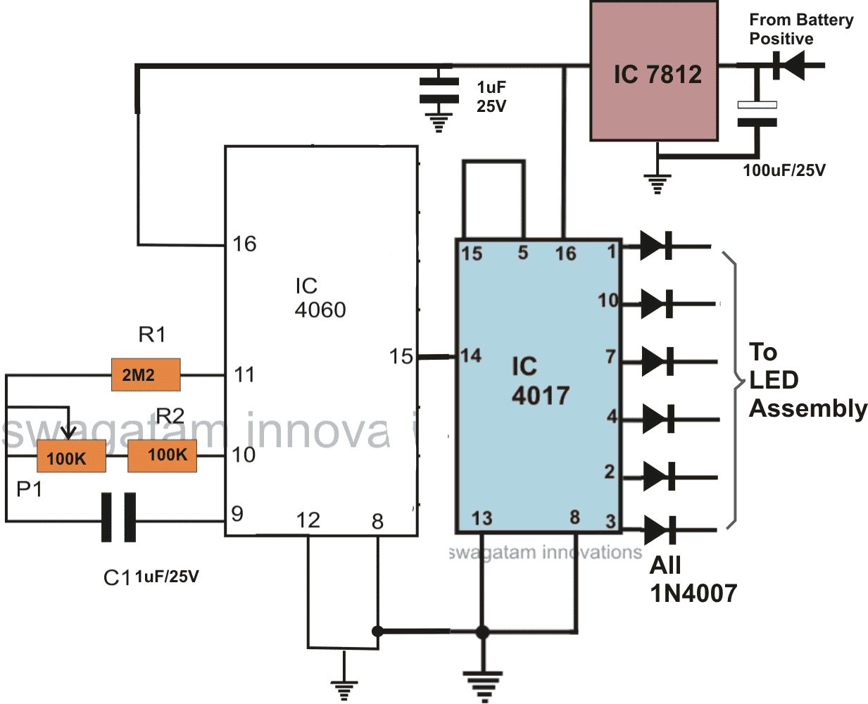
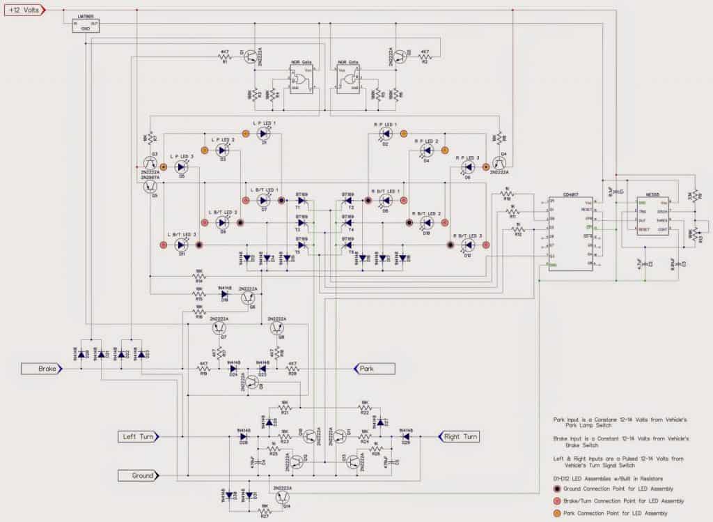
The CIRCUIT DIAGRAM can be divided into two sections, the first consists of the LED driver stage, where the IC 4017 forms the main LED sequencer and is configured in its usual counter/divider mode.
Only six channels of the IC 4017 have been used to avoid lengthy sequencing patterns and crowding of the LEDs.
Two arrays of LED are taken from the above outputs such that they "run" in opposite directions when switched ON, however both the channels are never run together since they are used for the LEFT, RIGHT turn indicator purpose and therefore only the relevant side is switched ON depending upon the vehicles turning side.
The IC 4060 is configured in its standard mode, as an oscillator and is used for driving the IC 4017 with its clock signals. With every rising peak of the clocks, the outputs of the IC 4017 shift from one pin out to the next in the shown order, making the connected LED illuminate sequentially.
The pot associated with the IC 4060 may be used for adjusting the sequencing speed as desired.
Left Right LED Sequence Layout
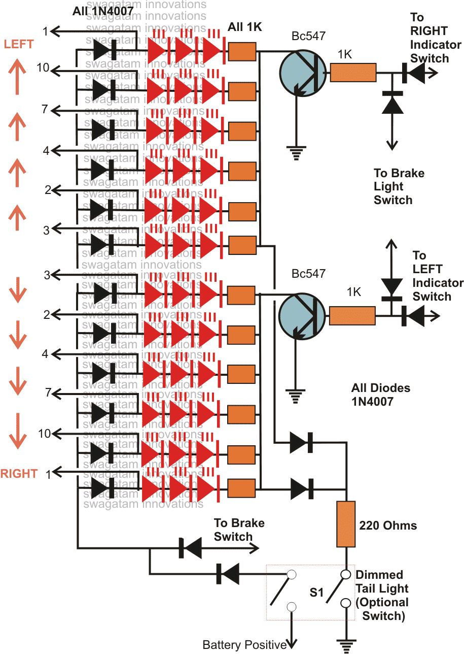
The LED stage consists of the LEDs arranged in a definite sequencing pattern as discussed in above explanation. The LEDs are connected to the IC 4017 outputs so that they are able to perform the intended sequencing or chasing function.
The LEDs are also discretely wired up to the different vehicle controls like the brake switch, the turn signal switches and an optional DIM tail light switch.
When the brake switch is applied, the LEDs light up all together brightly, indicating the application of the brakes.
When one of the turn signal switches is switched ON, say for example the LEFT turn signal is applied, the LED array positioned on the LEFT portion starts sequencing from center, toward LEFT, indicating the intended moving direction of the vehicle.
The above function is repeated toward the RIGHT side by the right portion LED array when the right signaling is made with the relevant switch.
A couple of optional switches (S1) may also be included and wired up with the LEDs as shown in the diagram. This provides a feature of operating the LEDs as a dim tail light indicator which stays switched all the time with a relatively lower brightness, however when the brakes are applied the LEDs light up brightly.
The driver circuit is powered through the IC 7812 which is a voltage regulator and provides safe operating stabilized voltage to the circuit, irrespective of the input fluctuations.
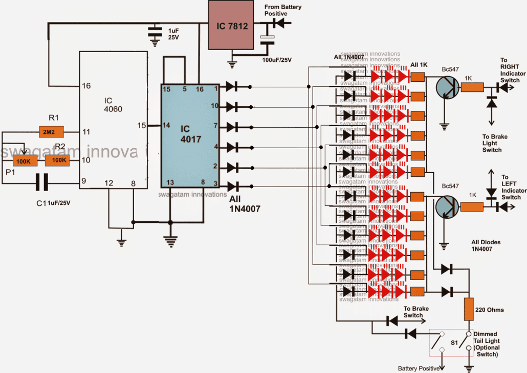
In the above position, the turn signals will also work, but is not recommended as the DIM light at the background may affect the signaling. The following image shows the complete combined circuit design of the above discussed two stages:
Complete Schematic Diagram
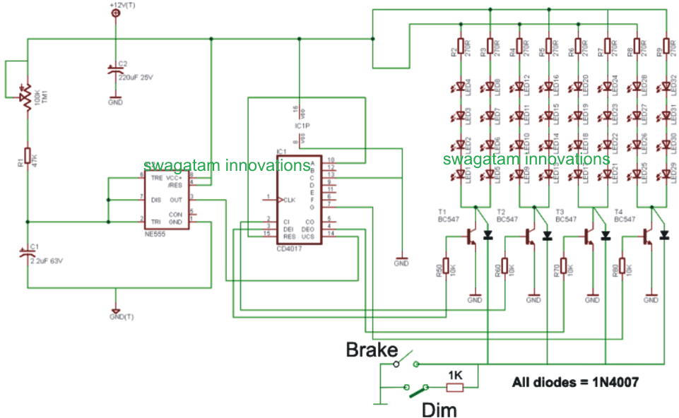
A simplified and scaled down version of the above explained car chasing light circuit with brake light and park light can be witnessed below:
The post illustrates an elaborate circuit design that can be used as an enhanced "chasing" LED tail light for cars and other vehicles, the design also includes the modification details for the associated turn signal and the park light systems. The idea was designed and presented by Mr. Jason.
The entire discussion may be referred to in the comment section of this post:
Sequential Turn Signal Indicator
Modified car chasing light circuit
The circuit description below explains the proposed modified car chasing light circuit, as presented by Mr. Jason:
Okay, I had a chance to work on it, but have not tested it on the breadboard yet. If this works, one 4017 and 555 timer chip can be used for both left and right turn signal.
The schematic
How the Circuit Functions
I hope you can understand what it is doing. The LED's I will be using have 3 wires out. One is ground, one is Brake/Turn, and one is Park. When just 12 volts is hooked up to the assemblies,
It seems that there are different resistors to control the brightness (a fixed amount) for the brake/turn, and for the Park. Which is a nice factory option from the LED assemblies themselves.
If I just use one wire (the brake/turn), and a potentiometer to adjust the brightness for the Park, I am thinking I would need a 19W potentiometer, and those are expensive.
Each LED assembly draws 246mA at 12.8 volts. If all 6 lights were on, that's 246mA * 12.8 volts = 18.89W of power. So, wiring them separately and using a common ground to switch them on and off, would eliminate the need for a potentiometer, since the resistors are built into the lights themselves.
I am using a NOR gate to turn off the Park LED's when the brake or turn signals are applied.
I am not sure on the resistor values. I've changed the Vcc for the 4017 and 555 to run off of the LM7805 voltage regulator. By doing that, I have also run the other inputs/outputs of those chips off of the LM7805 as well? I am not sure of the Capacitor and Resistor values needed then.
I'd like to switch all power to 5volts for less power consumption. Except for the LED supply voltage of course. that needs to stay the 12-14 volts coming straight from the wiring of the Truck.
I took your suggestion and added the transistor and the resistor to rapid discharge the 470uF capacitors so the LED's do not continue to sequence for 15 seconds AFTER the turn signals have been turned off.
As per your request, I have connected them to the last sequencing output of the 4017. It makes sense, and as you said, should work for turning off the LED's from sequencing.
If I can get this to work, I plan on building a circuit to allow up to the 8 sequencing LED's (available outputs for the 4017 since two are used to reset the 4017 and the SCR's).
I will do it using either dip switches or more simply, solder bridges. I will also make it so that solder bridges will be before and after a resistor of each LED, if a resistor is needed for standard LED's to be wired up.
I need to do this for my car, and my new lights will have 5 rows of LED's I will need to sequence instead of the 3 that my nephews truck has. So I'll need to design the circuit to work for both. Fun Stuff!
Using High Watt LEDs
Now let's discusses how to construct a chasing car tail light circuit using high watt amber LEDs. The idea was requested by Mr. Brian Walton.
Technical Specifications
I've been giving the project some further thought. I am wondering what changes might be needed to use single, higher power leds instead of the advised 5mm ganged in threes? So there would be 6 LED's rather than 6*3 5mm
The reason is that I have combined LED DRL & indicators on the front of my car, so I would like to retain the OEM look & feel at the rear - where I propose to use your excellent circuit design.
I'm thinking along the lines of the LEDS in the link below.
They are Osram Opto Diamond DRAGON Series GW Amber LED. They are designed for automotive use in DRL's and indicators.
They are 2.9v forward voltage and appear to take about 1.4A at typical lumens.
The LEDs above are not definitive but a suggestion in terms of output and style for my construction needs.
So my question is can the circuit take or how do I need to modify the circuit to take the extra power these LED's may take.
For info; from a practicalities point of view, I intend to have a separate driver circuit for each side of the vehicle - it makes installation simpler given i'm going to attach the pulse form the existing indicator
relay as discussed previously with you.
I hope you can advise me (again!) and many thanks for your devotion to the electronics hobbyist on the web.
Best wishes
Brian
Solving the Circuit Query
Thanks Brian!
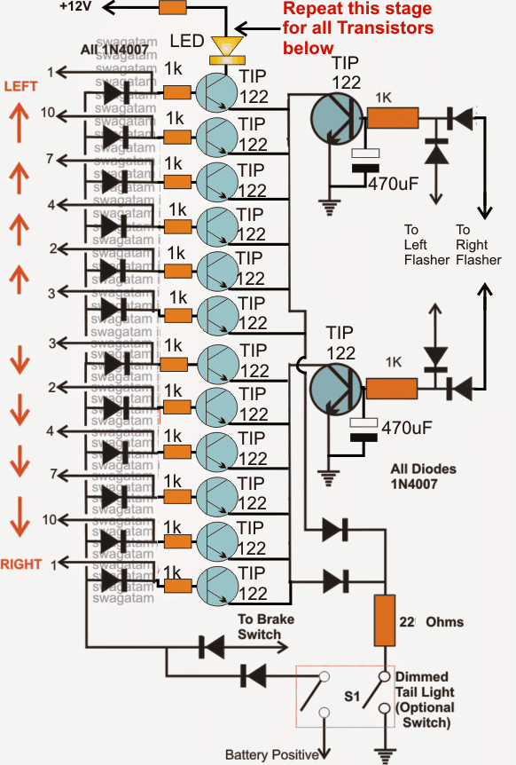
Incorporating higher wattage LEDs will need individual transistor buffers across the 6 outputs from the IC, it's actually very easy to implement.
I'll try to explain the connections verbally, although I am also thinking of updating a suitable diagram for this particular application, I may do it within a couple of days....in the meantime you could try doing the following mods in the above circuit:
Use TIP122 for the buffer transistors.
Connect the bases of the 6 transistors to the respective outputs of the IC 4017 via the indicated diodes. Make sure the base have individual series 1k resistors
The LEDs will need to be attached across the transistor collectors and the positive, the LEDs too must have their own series limiting resistor
The LED resistors could be calculated using the following formula:
R = (Us - LEDfwd)/I
where Us is the supply voltage,
LEDfwd is the optimum glow voltage of the LED or the forward voltage drop spec.
I is the optimum current for the LED as specified in its datasheet.
That's all..... now your circuit is ready and would be capable of handling any type of high watt LEd in the range....
Circuit Diagram
Draw A Simple Brake Light Circuit
Source: https://www.homemade-circuits.com/how-to-make-car-led-chasing-tail-light/
Posted by: calhounthesto.blogspot.com
0 Response to "Draw A Simple Brake Light Circuit"
Post a Comment